 2026-06-16
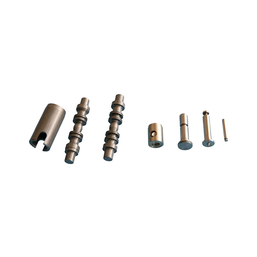
 En præcisionsmotoraksel er en bearbejdet roterende komponent, der overfører drejningsmoment fra en motors rotor til en ekstern mekanisk belastning - men ordet "præcision" har en specifik ingeniørbetydning, der adskiller disse dele fra standard kommercielle aksler. En præcisionsmotoraksel er defineret af stramt kontrollerede dimensionstolerancer, strenge krav til geometrisk nøjagtighed (rundhed, cylindricitet, rethed) og overfladefinishspecifikationer, der gør det muligt for akslen at arbejde ved høje hastigheder, bære nøjagtige belastninger og interface pålideligt med lejer, koblinger, indkodere og drevne komponenter over en lang levetid.
In practical terms, a standard commercial shaft might be manufactured to an h8 or h9 tolerance class with surface roughness in the Ra 1.6–3.2 µm range — adequate for general industrial use but too loose for applications demanding accurate positioning, low vibration, or long bearing life at high rotational speeds. A precision motor shaft derimod fremstilles typisk til h5, h6 eller snævrere toleranceklasser med overfladeruhed mellem Ra 0,2 og Ra 0,8 µm ved lejetapper og koblingssæder. Ved disse toleranceniveauer måles dimensionsvariation i mikrometer, og akslens geometri - dens rethed, udløb og cylindricitet - skal verificeres med instrumenter, der er i stand til at løse sub-mikron afvigelser.
This level of accuracy matters because even small deviations in a precision motor shaft directly translate into performance problems: a shaft journal that is 10 µm out of round will cause the bearing to experience cyclic loading at rotational frequency, generating vibration and accelerating bearing fatigue. En aksel med 20 µm udløb ved koderens monteringssted vil producere positionsfejl, der forringer nøjagtigheden af en servokontrolsløjfe. I medicinsk udstyr, halvlederudstyr, rumfartaktuatorer og højhastighedsbearbejdningsspindler er disse afvigelser ikke acceptable - og det er det miljø, præcisionsmotoraksler er designet til.
Materialevalg til en præcisionsmotoraksel er drevet af den nødvendige kombination af styrke, bearbejdelighed, hårdhed, korrosionsbestandighed og magnetiske egenskaber. Intet enkelt materiale udmærker sig i alle disse egenskaber samtidigt, hvorfor præcisionsskaftmaterialer er nøje tilpasset de specifikke krav til hver applikation.
Medium-carbon steels such as AISI 1045 and alloy steels such as AISI 4140 and 4340 are the workhorses of precision motor shaft manufacturing. They offer an excellent balance of tensile strength (typically 600–1,000 MPa in the normalized or quenched-and-tempered condition), good machinability, and the ability to be surface-hardened by induction hardening or case carburizing to achieve surface hardness values of 55–62 HRC at bearing journals while retaining a tough, ductile core. This combination — hard surface for wear resistance and fatigue strength at stress concentration points, tough core for impact resistance — is ideal for servo motor shafts, stepper motor shafts, and general industrial precision motor output shafts where torque loads are significant and surface durability is critical.
AISI 4140 chromium-molybdenum steel is particularly popular for precision motor shafts because it responds predictably to heat treatment across a wide range of section sizes, machines cleanly to fine surface finishes, and maintains dimensional stability after heat treatment when stress-relief annealing is included in the manufacturing sequence. Til anvendelser med meget høj styrke - såsom aksler i rumfartsservoaktuatorer eller direkte drevne motorer med højt drejningsmoment - giver AISI 4340 nikkel-krom-molybdænstål trækstyrker over 1.200 MPa med fremragende sejhed.
Præcisionsmotoraksler i rustfrit stål er påkrævet, hvor som helst driftsmiljøet involverer fugt, ætsende kemikalier, fødevarekontakt eller renrumsforhold, der forbyder brugen af ubelagt kulstofstål. AISI 303 og 304 rustfrit stål anvendes til let belastede aksler, hvor korrosionsbestandighed er den primære drivkraft, og kravene til mekanisk styrke er moderate. For higher-strength applications, martensitic grades such as AISI 416 or 440C are heat-treatable to hardness levels above 55 HRC, providing both corrosion resistance and the surface hardness needed for long bearing life. AISI 17-4PH udfældningshærdende rustfrit stål bruges i krævende applikationer, der kombinerer høj styrke (over 1.000 MPa), moderat korrosionsbestandighed og fremragende dimensionsstabilitet efter ældningshærdning - hvilket gør det til et almindeligt valg for præcisionsaksler i rumfarts- og medicinsk udstyrsmotorer.
In certain motor designs — particularly brushless DC motors with Hall effect sensors, MRI-compatible medical motors, and motors operating near sensitive magnetic field measurement equipment — the shaft must be non-magnetic to avoid disturbing the motor's magnetic circuit or the surrounding environment. Ikke-magnetiske præcisionsmotoraksler er almindeligvis fremstillet af austenitisk rustfrit stål (304, 316), titanlegeringer (Ti-6Al-4V) eller beryllium-kobberlegeringer. Titanium shafts additionally offer very high strength-to-weight ratios and excellent fatigue resistance, making them valuable in weight-critical aerospace and robotics applications despite their higher material cost and greater machining difficulty compared to steel.
The dimensional and geometric specifications of a precision motor shaft are not arbitrary — each tolerance requirement exists because a specific aspect of shaft geometry directly affects a measurable performance outcome. Understanding which tolerances matter most for each application zone of the shaft helps engineers specify correctly and avoid over-specifying features that add cost without adding performance.
| Shaft Feature | Typical Precision Tolerance | Performance Impact if Out of Tolerance |
| Bearing journal diameter | IT5 / IT6 (h5, k5, m5) | Incorrect bearing fit, vibration, premature bearing failure |
| Coupling or pulley seat diameter | IT6 / IT7 (h6, k6, j6) | Slippage under torque or fretting corrosion at interface |
| Runout at bearing journals (TIR) | ≤ 2–5 µm | Vibration at rotational frequency, reduced bearing life |
| Runout at encoder mount | ≤ 2–3 µm | Position feedback error, servo control instability |
| Shaft straightness | ≤ 5–10 µm over shaft length | Bow-induced vibration, uneven bearing load distribution |
| Cylindricity at bearing journals | ≤ 2–4 µm | Non-uniform bearing race loading, rolling element fatigue |
| Keyway position (angular) | ±0.1° to ±0.05° | Misaligned key torque transmission, fretting wear |
| Surface roughness at bearing seats | Ra 0.2 – 0.4 µm | Scoring of bearing inner race, fretting corrosion |
The relationship between shaft tolerances and ISO system tolerance grades is worth understanding for anyone specifying or inspecting precision motor shafts. The ISO standard IT grade system grades tolerances from IT01 (tightest) through IT18 (loosest). For precision motor shaft bearing journals, IT5 and IT6 are the standard grades — these correspond to diameter tolerances of approximately 6–11 µm for a 20mm journal diameter and 8–13 µm for a 30mm journal diameter. For ultra-precision applications such as high-speed spindle motors or surgical robot actuators, IT4 or tighter tolerances may be specified, requiring grinding and lapping operations to achieve.
The manufacturing sequence for a high-accuracy motor shaft is carefully designed to minimize the dimensional distortion introduced at each processing step and to ensure that the final machining operations are performed on a stable, stress-free workpiece. Shortcuts in this sequence — such as skipping stress relief after rough machining, or grinding before heat treatment — consistently produce shafts that fail to hold tolerance in service as residual stresses relax during operation.
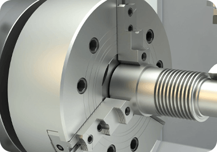
The manufacturing process begins with turning the bar stock or forging to rough dimensions on a CNC lathe, leaving 0.3–0.5mm of stock on all functional surfaces for subsequent grinding operations. Centre holes are drilled at both ends of the shaft to precise dimensional standards — these centres serve as the datum reference for all subsequent turning, grinding, and inspection operations, so their accuracy is foundational to the accuracy of every subsequent dimension. After rough turning, a stress relief heat treatment cycle (typically 550–650°C for steel alloys, held for 1–2 hours and slow-cooled) removes residual machining stresses that would otherwise distort the shaft when material is removed in subsequent finishing operations.
For shafts requiring surface hardening, the heat treatment stage follows rough machining and stress relief. Induction hardening is the most common method for precision motor shafts — it allows bearing journals and other wear-critical zones to be selectively hardened to 55–62 HRC while leaving transition zones and threaded features at lower hardness to prevent brittleness. The depth of the hardened case (typically 1–3mm for most motor shaft diameters) is controlled by the induction coil geometry, frequency, and dwell time. After hardening, a low-temperature tempering cycle (150–200°C for 2 hours) relieves quench stresses and stabilizes the martensite structure without significantly reducing surface hardness. The shaft is then straightened if necessary — heat treatment invariably introduces some bow — before proceeding to finish grinding.
Cylindrical grinding between centres is the primary finishing operation for precision motor shaft bearing journals, coupling seats, and other critical diameter features. The shaft is mounted on its centre holes and traversed past a rotating abrasive wheel that removes material in controlled increments, achieving the final diameter, roundness, cylindricity, and surface finish in a single setup. Modern CNC cylindrical grinders with in-process gauging can achieve diameter tolerances within ±1–2 µm and roundness within 0.5–1 µm under stable thermal conditions. The wheel specification — grain type, grit size, bond, and structure — is chosen based on the shaft material and the required surface finish: CBN (cubic boron nitride) wheels are commonly used for hardened steel precision shafts because they cut more precisely, wear more slowly, and generate less heat than conventional aluminium oxide wheels.
Precision motor shaft inspection is performed on temperature-controlled metrology equipment, typically in a climate-controlled room maintained at 20°C ±1°C, since thermal expansion of steel is approximately 11.7 µm/m/°C — a temperature variation of just 5°C across a 200mm shaft would produce a dimensional change of 11.7 µm, enough to shift a shaft from within tolerance to out of tolerance at IT5 grade. Diameter measurements are made with air gauging or contact probes on a CMM (coordinate measuring machine). Runout and straightness are measured with a precision V-block setup or in a precision lathe using a dial indicator or electronic probe with sub-micron resolution. Surface roughness is measured with a contact profilometer. All measurement results are documented in a first article inspection report (FAIR) that becomes part of the shaft's quality record.
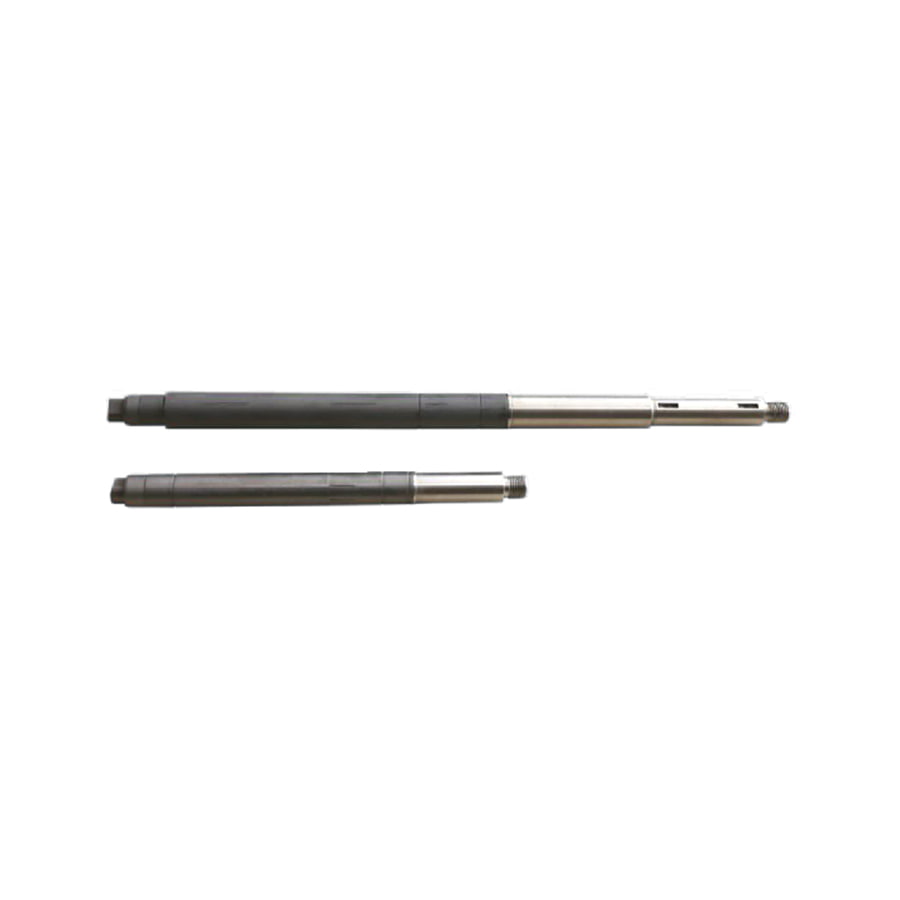
Ud over grundlæggende dimensionsnøjagtighed inkorporerer præcisionsmotoraksler specifikke designfunktioner, der muliggør pålidelig drejningsmomentoverførsel, sikker komponentmontering og nem montering og demontering. Hver funktion skal være omhyggeligt designet og præcist udført for at udføre sin tilsigtede funktion uden at indføre stresskoncentrationer eller monteringsbesvær.
Keyways er den mest almindelige momentoverførselsfunktion på præcisionsmotorudgangsaksler. En parallelkile placeret i matchende kilespor i både akslen og navet på en kobling eller remskive overfører drejningsmoment gennem forskydning på tværs af nøgletværsnittet. Til præcisionsanvendelser holdes kilesporsdimensioner til snævre tolerancer - typisk JS9 eller N9 på bredden - for at minimere sløret og forhindre slitage ved nøgle-kilens grænseflade. Kilesporet skal placeres for at undgå det svageste tværsnit af akslen, og kilesporets hjørneradier skal være generøse nok til at reducere spændingskoncentrationsfaktoren, som er et almindeligt initieringssted for træthedsrevner på motoraksler.
Involutte splines bruges, hvor der kræves højere momentkapacitet, selvcentrering eller aksial glideevne. Splined precision motor shafts are common in servo motor applications where the driven component must slide axially during assembly or operation. Den involutte notprofil tillader selvcentrering under belastning, hvilket reducerer bøjningsmomenterne ved aksel-nav-grænsefladen sammenlignet med en parallel nøgleforbindelse.
The end of a precision motor shaft typically incorporates features for axial retention of mounted components. En gevindende med en møtrik og en skive, en akselrille til en låsering eller et tappet hul til en holdebolt er alle almindelige løsninger. Gevind på præcisionsmotoraksler skal skæres rent, og gevindformen skal være nøjagtig nok til at tillade, at en møtrik kan strammes uden binding, og gevindet skal placeres så langt som muligt fra lejetappene for at minimere spændingskoncentrationens interaktion. Flader bearbejdet på akselenden er nogle gange tilvejebragt for at tillade, at akslen holdes stationær under kobling eller remskiveinstallation uden at beskadige præcisionslejeoverfladerne.
Diameterændringer langs en præcisionsmotoraksel - fra lejetappen til rotormonteringsdiameteren eller til udgangsakslens ende - er designet som skuldre med kontrollerede filetradier ved overgangen. Filetradius er en kritisk udmattelsesdesignparameter: Et skarpt hjørne ved en diameterændring skaber en høj spændingskoncentrationsfaktor (Kt), som dramatisk reducerer skaftets udmattelsesgrænse. Til roterende bøjningsapplikationer (som er den dominerende belastningstilstand for de fleste motoraksler), kan en forøgelse af filetradius fra 0,5 mm til 2,0 mm ved en given skulder forbedre udmattelseslevetiden med en faktor på 3-5. Præcisionstegninger af motoraksel specificerer minimumskantradier ved alle skulderovergange og kræver ofte, at disse radier fremstilles ved slibning i stedet for drejning, for at sikre, at de er glatte og fri for bearbejdningsmærker, der kan forårsage udmattelsesrevner.
At forstå, hvordan og hvorfor præcisionsmotoraksler fejler, giver ingeniører mulighed for at designe mere robuste aksler, vedligeholdelsesteams til at identificere tidlige advarselsskilte og indkøbsteams til at evaluere akselkvaliteten mere kritisk. Følgende fejltilstande tegner sig for langt størstedelen af servicefejl på præcisionsmotorakslen.
Specifying a precision motor shaft — whether for a new motor design, a motor rebuild, or a custom shaft for a special application — requires working through a structured set of engineering decisions. At tage genveje i denne proces fører konsekvent til enten overspecificerede (dyre) eller underspecificerede (upålidelige) aksler.
 Kategori
Fenglan er Producent af elektriske præcisionsdele i Kina, Producenter af præcisionsdele til biler og Leverandører af industrielle præcisionsdele. Din pålidelige partner inden for fremstilling af dele og komponenter siden 2010
 Tel: +86-13861233850
  E-mail: [email protected]
  Add: No.60, East Zhuanghe Road, Chunjiang Town, Wei Village, Xinbei District, Changzhou City, Kina
  Privatliv


 +86-13861233850
 2025-09-17